Arduino Stepper Motor Serial Control Records

This driver board was designed to be affordable, compact and have more features than previous versions of serial-controlled motor drivers. Its main advantage is the variability of drive levels making fine control adjustments a possibility. Features: • 1.5 A peak drive per channel, 1.2 A steady state • Operates from 3 to 11 volts with 12v absolute max • 3.3v default VCC and logic • Max VCC in of 5.5v • 127 levels of DC drive strength. • Controllable by I2C, SPI, or TTL UART signals • Direction inversion on a per motor basis • Global Drive enable • Expansion port utilizing I2C, allows 16 additional drivers • Exposed TO-220 heat sink shape • Several I2C addresses, default UART bauds available • Bridgeable outputs • Optional fail-safe and diagnostics available. • Configurable expansion bus bit rate to 50, 100, or 400 kHz. • Configurable expansion bus update rate from 1ms to 255ms, or by command only Covered In This Tutorial This tutorial covers basic usage of the motor driver.
It shows how to connect it to I2C, SPI, or UART at 3.3V levels, and how to attach more drivers to the master and control them all independently. It also shows some common motors that can be used without heatsinks. Required Materials This tutorial explains how to use the Serial Controlled Motor Driver Breakout Board with an Arduino or direct serial. To follow along, you’ll need the following materials: • or – to communicate with the SCMD. • Some DC motors, such as: • • •. Terminology This guide and related documentation uses a few terms with specific meanings. When User and Expansion are used, it is referring to the physical pins of the connection.

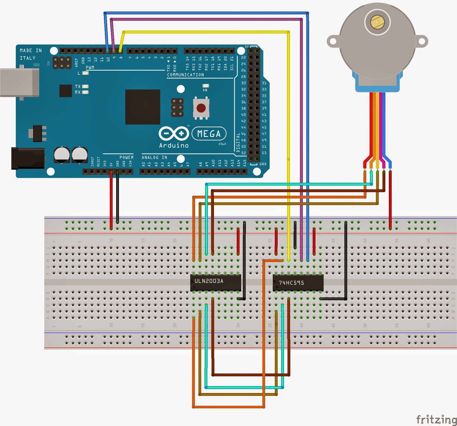
The CoolTerm serial terminal application showing the hexadecimal view. NOTE: only one program can control a serial port at a time. When you’re not using a given program, remember to close the serial port. You won’t be able to re-program the Arduino module if you don’t, because the serial terminal program will have control of the serial port. Typically stepper motor control isn't necessarily done in software but in hardware. See this stepper motor driver for an example. The driver allows you to set bits to control how much you would like to step (full, half, quarter, etc.), and takes care of actually providing driving current to the motor.
Movie in hindi 2017. The chronicles of narnia 1 (2005) full movie hindi dubbed download (5) narnia 1 full movie in hindi free download 720p (4) Filmyhit Narnia (3) index of narnia hindi (3) Index of narnia 1 in hindi (2) katmoviehd the chronicle of narnia (2) the chronicles of narnia the lion the witch and the wardrobe full movie download at katmovies (2).
When Master and Slave are used, it matches the I2C behavior on the expansion port, and refers to the connected chain of SCMDs. • User Port – Connects the user’s project to the master SCMD and is unused on slaves. • Expansion Port – Connects a single master and up to 16 slaves, and should never be connected to the user’s project. • Master – The SCMD that is connected to the user’s project. Ibp 115 2 crack fully working torrents free. Also, it is the I2C master on the expansion port • Slave – A SCMD that is only connected to a master SCMD by way of the expansion port.
Note: The config in and out pins of the expansion port may sometimes be connected to the user’s project for error checking and mitigation purposes. Motor Polarity – The driver and this document often omit motor polarity. This is because polarity to spin direction is not standardized, and it is assumed the user will attach them backwards 50% of the time. Each motor channel is independently configurable for what is thought of as ‘forward’ spin by command. It is assumed that the user will first attach the motors, then decide which channels need to be inverted and issue inversion settings at boot time.